VANTEC  
 
Speed Controls R/C Set Servos Interface Videoh Audioh Other
 
   
View Cart

Now Accepting:

Computer commanded Dual Forward Reverse speed controllers

Not Current Available Online
Not Yet Available Online
 
  • COMPUTER CONTROLLED MACHINERY

  • INTELLIGENT MOBILE ROBOTS

  • DUAL CONTROLS IDEAL FOR TANK TYPE STEERING WITH RIGHT & LEFT MOTORS

  • CHOICE OF ELECTRO-DYNAMIC BRAKING

  • 5-30VDC

  • DRIVER VERSIONS FOR 1-30 AMPS

  • FAST PARALLEL PORT COMPATIBLE

  • 8 BITS PLUS STROBE & SELECT LINE

Driver.JPG (1133 bytes)


The CDFR DRIVER family of speed controls operate two independent electric motors from a single conventional 8 bit parallel computer port. These smooth proportional duty cycle controllers run in both directions and clever coding facilitates building your system with or without an adjustable electro-dynamic brake. Once commanded the motors continue to run without additional commands being required thus freeing your computer for other computations. By using the parallel port configuration instead of a serial port both motors may be commanded within microseconds of each other to facilitate coordinated X-Y closed loop servo operations. The acknowledge, busy and other handshake lines are not required; just 8 data bits and a strobe. CDFRs have also been used to command proportional hydraulic valves to control hydraulic motors. Much of the circuitry in the CDFR is patterned after our proven RDFR Radio/Control commanded speed control.

Inside each CDFR are two rugged forward/reverse speed controls designed without relays for professional applications requiring repetitive forward to reverse commands. The outputs are Pulse Width Modulated full H-bridge circuits originally designed for Permanent Magnet DC wheel chair motors. N-channel power MOSFETs are paralleled in each H-bridge leg to achieve the specified amperage. In contrast to hobby controllers VANTEC's MOSFETs are all properly thermally mounted flat to the metal heat dissipating case with special insulating washers. The case is electrically isolated and there are no exposed transistors to accidentally short out.

The circuitry PWModulates the bottom half of the bridge while holding the diagonal upper bridge leg on in order to effect efficient re-circulating currents in the motor. Electro-dynamic braking shunts the motor by modulating both top legs of the bridge. The PWM rate for this braking is under the control of your computer.

Output current through the MOSFETransistor is compression limited above a threshold by PWM duty cycle limiting. Some short circuit protection is provided.

CHOOSING THE RIGHT MODEL: The SPECIFICATION CHART shows single output or one motor's ratings. Measure your motor's continuous running current under actual normal mechanical load. Or determine your DC PM motors armature terminal resistance by consulting specifications or measurement. The armature resistance measurement cannot be done with conventional ohm meters. However, it may be simply measured by mechanically locking the motor shaft and reading the current drawn while briefly powered from a fresh alkaline 1.5 volt "D" cell. The SELECTOR CHART shows armature resistance in "D" cell amps as well as ohms. Choose a CDFR at your operating voltage with lower Ohms or higher Amps than your motor. VANTEC surge ratings express useable motor starting surge current over a realistic 5 second period unlike some competitor's microsecond peak ratings. All current ratings are genuine American Amperes at the 338 Hz PWM chop frequency. For the extra smooth operation and silent running at the 21.6KHz PWM rate these amperages must be de-rated 30%.

SELECTOR CHART
  V Ohm "D"amps Recommened Part#
5 0.09 12 CDFR21
5 0.06 NA CDFR22
5 0.04 NA CDFR23
9 0.17 7 CDFR21
9 0.12 9 CDFR22
9 0.07 13 CDFR23
12 0.23 5.3 CDFR21
12 0.16 7 CDFR22
12 0.11 10 CDFR23
18 0.34 3.7 CDFR21
18 0.24 5.2 CDFR22
18 0.18 6.5 CDFR23
24 0.46 2.9 CDFR21
24 0.32 4 CDFR22
24 0.23 5.7 CDFR23
30 0.57 2.3 CDFR21
30 0.40 3.2 CDFR22
30 0.28 4.6 CDFR23

These instructions are for the CDFR21 through CDFR23. PLEASE read and understand them before connecting power. Consult factory for higher power or voltage CDFR computer interface controllers similar to the RDFR33-63E, or a SPI microprocessor style interface.
  Voltage Range Con't Amp Start Amp LegLoss Size Wght Oz Wire AWG Price Comments
CDFR21 5 30 14 70 0.009 4.25 X 2.7 X 1.37" 8 20 239.95 0
CDFR22 5 30 20 70 0.005 4.25 X 2.7 X 1.37" 9 16 269.95 0
CDFR23 5 30 30 70 0.003 4.25 X 2.7 X 1.37" 9 14 324.95 0


JUMPERS: The jumpers are factory set in the parked OFF position for the most popular mode which IGNOREs the device select line and utilizes a 338 Hz PWM chop frequency. Install JP1 closed to select the 21.6KHz rate: be advised this higher chop rate will generate more RFI and may require RFI filters.

JP2 and JP3 establish the operation of the DEVICE SELECT line. Most applications use only one CDFR to an 8 bit port and thus use the IGNORE position. The other two possibilities are active high and active low. Without any additional hardware two CDFRs can be commanded by one port and a 9th signal to drive the SELECT. On a PC port special software manipulation of the handshake lines can drive the DEVICE SELECT since they are not normally used to talk to the CDFR. With two 8 bit ports eight CDFR's may be commanded still without extra hardware. Add simple de-multiplexing logic to yield up to 256 CDFR's under the control of two ports. JP4-JP8 are not used in this product. OFF=parked. Jumper ON=installed =present= closed.

DEVICE SELECT(Pin20)
  JP2 JP3
Ignore OFF OFF
Active HI ON ON
Active LO ON OFF


IBM PC PRINTER PORT:
The CDFR parallel interface is compatible with an IBM compatible PC's printer port except that the handshaking lines are not used. Like a printer, commands are clocked into the CDFR on the falling edge of the \STROBE line, including the DEVICE SELECT if used. Set up time for the data prior to the \STROBE's fall is 0.1us and the data hold time is 0.5us. The \STROBE itself must be low for a minimum of 0.2us. If you use BASIC's LPRINT command please tie Busy, PaperEnd and SelectIn low to ground via a 100 ohm resistor.

Speed of your motor is by direct command of the PWM duty cycle (open loop control) with data bits D0 (LSB) through D5 to provide 61 even steps between 0% and 100%. Bit D6 controls motor direction and D7 determines which motor is commanded. There are four commands for 0%=off which control   electro-dynamic braking and the optional mechanical brake release.   By alternately commanding the proper pair of "off" codes your computer can vary the braking duty cycle.  Most applications program a brake ramp of 0-100% duty cycle motor shunting. Alternate D6=0 & 1 while holding D0=1 at a maximum chop rate of 900 HZ. Interlace the commands to both motors for simultaneous braking. The braking scheme sacrifices very low duty cycle commands that are below a practical operating point for most motors.

The test programs used by VANTEC are available only on our WebSite under Applications, Manuals and Software; CDFRLPT1.BAS for LPT1 as QuickBasic 4.5 text readable, CDFRLPT1.EXE as executable version   and CDFRLPT2.EXE as LPT2 executable. Inspection of the .BASic source code is helpful to understand operation. Although these test programs run fine on our computer under the Win95 DOS re-boot, please understand that machines and ports vary widely so these test programs may or may not run on your computer. We do not support them.

COMMAND  CODE  CHART  
VEHICLE MOVING: (Mech Brake Released)
D7 D6 D5 D4 D3 D2 D1 D0    
M D 1 1 1 1 1 1 100% SPEED [(D5 thru D0) +1]/64ths
M D 1 1 1 1 1 1 98% SPEED [(D5 thru D0) +1]/64ths
. . . . . . . .     SPEED  
M D 0 0 0 1 0 0 7.8% SPEED [(D5 thru D0) +1]/64ths
M D 0 0 0 0 1 1 6.2% SPEED [(D5 thru D0) +1]/64ths
M D 0 0 0 0 1 0 4.7% SPEED, SLOWEST [(D5 thru D0) +1]/64ths
  0 FORWARD          
  1 REVERSE         D6 DIRECTION BIT
                   
ELECTRO-DYNAMIC BRAKING: Alternate D6 Hi-Lo-Hi-Lo
M 0 0 0 0 0 0 1 0% Shunt Brake (open) Mech Brake Off (released)
COASTING
M 1 0 0 0 0 0 1 100% Shunt Brake (short) Mech Brake Off (released)
ELECTO DYNAMIC ONLY
                   
VEHICLE PARKED AT REST:  
M 0 0 0 0 0 0 0 0% Shunt Brake (open) Mech Brake On ONLY
(not released)
M 1 0 0 0 0 0 0 100% Shunt Brake (short) Mech Brake On
(not released)  BOTH BRAKES
D7 D6 D5 D4 D3 D2 D1 D0    
                   
0 Select MOTOR 1      
1 Select MOTOR 2     D7 SELECT MOTOR BIT


OPTIONAL MECHANICAL BRAKE RELEASE or CLUTCH ENGAGEMENT: The other braking combinations using D0 allow for command of the optional mechanical brake output. It provides a 2 amp output current sink that turns on when there's a command for motion. With a stop command it goes off after a short delay. Connect at the single terminal block connection BRK. Install a flyback diode across your coil to protect the CDFR.

WIRING: Use proper static precautions while wiring; particularly the parallel data interface. Follow the layout schematic. Do not power the CDFR from batteries under charge, battery eliminators or chargers without consulting factory.

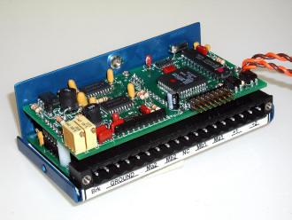
POWER & MOTOR: Observe battery polarity. The SPEC CHART shows the minimum size wire for the battery power and motor wiring; it is the size to use for each of the double wires. You must use double wiring to the Ma1, Mb1, Ma2, Mb2, +1 and +2 nodes on the handy plug in terminal block. We recommend you run the double wires all the way to their termination point; for example; the motor terminals. Screw torque will effect the connection resistance so tighten them! We have provided 4 connection screws for the ground node. Use all four as a massive parallel GROUND per the wire size indicated in the SPEC CHART. There are modes (perhaps going forward in your project!) where all the current of your two starting motors goes through the ground!

Wire with the minimum length wire practical and keep this wiring separated from the computer and parallel data interface. Ground your chassis at a single point but don't use the chassis to conduct current. Use separate regular-blow fuses to feed the +1 and +2 power terminals; select the smallest fuse which will support your normal operation but no larger than rated surge current. Install a .001ufd ceramic disc capacitor directly across each motors brushes and between each brush and their motor case for RFI protection.

PARALLEL DATA INTERFACE: Noise in the command data lines will result in improper operation. Use a #18 or equivalent in combined conductors for the ground; for example: some ribbon cable schemes use a ground for every other wire. Longer runs and FCC requirements may indicate shielded cable. Use the minimum length wire practical and don't bundle it with other data or power wiring. These CDFR models have a common ground between the logic and the power circuitry; use caution to avoid ground loops. Any circuit paths, including unintentional sneak path, that forces the ground between your computer and the CDFR to conduct current will modulate noise onto the data. We recommend initial testing and learning operation of the unit on a test bench with a completely separate motor battery running small unloaded test motors. Guard against static.

The parallel interface is a 24 pin DIP socket typically used for 24 pin Skinny-DIP Integrated Circuits like the 87C751.  It's pins are numbered like an IC with pin 1 through pin 12 down one side and pin 13 through pin 24 up the other side such that pin 1 and pin 24 are right across the .300" width from each other, at the notched end as indicated by the white printed nomenclature.  The socket is labeled U6 at the notch end and pin 1 is adjacent to the U in U6.

PARALLEL INTERFACE
IBM
-PC
Sig
Name
CDFR 24 Pin
DIP connector
Sig
Name
IBM
-PC
....Front Edgeof PWB....
DB-25 DB-25
6 D4 1 | - | | - | 24
5 D3 2 | | _ | | 23 D5 7
4 D2 3 | | 22 D6 8
3 D1 4 | | 21 D7 9
2 D0 5 | | 20 Dev Sel
NotRqd
17
6 | | 19 /Strobe 1
7 | | 18
8 | | 17
9 | | 16
10 | | 15
11 | | 14
18 Ground 12 | _ _ _ _ _ | 13
19 Ground
20 Ground
21 Ground
22 Ground
23 Busy 11 100 ohm to Ground
24 Paper 12 100 ohm to Ground
25 /On-Line 13 100 ohm to Ground


MOUNTING:
Don't mount the unit directly adjacent to your computer. Simultaneous operation of both halves at maximum ratings may require additional cooling air or mounting the CDFR side-opposite-the-terminal-block to additional heat sinking. Usually the metal frame of your project is sufficient. No special heatsinks are required. While mounting remove the cover to monitor the mounting screw length; screw should not thread into the case move than 1/8".

The CDFR has a limited one-year warranty based upon a nominal repair charge for units not tampered with or abused. Details available on our Warranty page.

Note: Our products are not safety devices nor for use in life-critical or life support systems. Specifications and price subject to change without notice. Patented. Some trade names, trademarks & content owned by others.

   
Sales: (800) 882-6832

 Home Page

Contact Us

Copyright 1998-2011 VANTEC, All Rights Reserved
460 Honeycutt Dr.  Grants Pass, OR 97526
 Switchboard: (541) 471-7135
FAX: (541) 474-3987 
Enable JAVASCRIPT for best performance

 
Application Help Terms and Conditions Home Browse Catalog Testimonials Affiliates Manuals Repairs About Us Contact Us Top of Page Speed Controls R C Sets Servos Interface Videoh Audioh Other