| The HITCHIKER
series provides the extra R/C channels to totally control your hobby robot, special EFX
project, or detail your 1/4 scale R/C plane. It is perfect for controlling submarines and
their complex plumbing. Making your dream scale R/C boat fully operational is now easier
than ever. Eliminate fussy servo-cammed microswitch kluges forever.
All HITCHIKER products are compatible with Futaba's excellent Pulse Code Modulation
method trademarked as PCM1024, only. Futaba offers a number of radio systems, both wheel
and stick types using PCM1024. For our KH832, KH816 & KH812 complete KeyKoder systems
we chose the Futaba FP-8UAP R/C set. PCM1024 is a significant improvement over FM because
it transmits the servo commands as digital words with special mathematical properties that
facilitate accurate reception. Servo jitters are a thing of the past. For a detailed
understanding of The PCM Advantage see pcmadv.htm.
VANTEC fully harnesses Futaba's coding to reliably pack additional controls onto one
of the Futaba R/C servo channels. The new controls are independent and operate
simultaneously. The remaining conventional channels are not affected. The variety of
KeyKoder Devices is described on the page #KeyKoder
Technology but by far the most popular devices are the 12, 16 and 32 channel KeyPad
additions that this document describes.
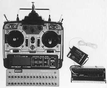
VANTEC recommends our complete systems that include the entire Futaba FP-8UAP R/C set
with 8 conventional servo channels, servos and all, plus the HITCHIKER KeyPad and
Receptor; we warranty the entire system.
The KH816 has 7 conventional servo channels and 16 KeyKoder on-off switch channels for
23 channels total.
The KH832 has 7 conventional servo channels and 32 KeyKoder on-off switch channels to
yield 39 channels total. Generally these versions are employed in boats and robots.
The KH812 complete system has 7 conventional servo channels and 12 added KeyKoder
channels. It's KeyKoder Receptor features 8 two or three position servo ouputs but only 4
electronic switches and finds use primarly in model aircraft. It has 19 channels total.
The switches can be used to control lights, engine ignition and starting. This system uses
the 16 switch transmitter KeyPad. Specifications and pictures on the KeyKoders are on page
6.
THE TRANSMITTER INSTALLATION: The Hitchiker KH16T or KH32T KeyPad snaps onto the base
of your Futaba FP-8UAP or FP-7UAP transmitter with your thumb to create 12, 16, or 32 new
on-off channels.
The KeyPad understands and "speaks" PCM1024; it interjects its new data onto
one of the regular servo channels. This means you lose the normal operation of the
selected channel; normally the retract switch channel 5 is sacrificed.
At the back of the KeyPad is a 3 wire cable with a 6 pin DIN connector that plugs into
the Futaba trainer connector. You cannot use the original trainer feature and the KeyPad
simultaneously.
FOR THE '8UAP the back of the KeyPad case has two slotted hooks that capture the back
legs of the Futaba case. Hook these on first. Then snap the front of the KeyPad case over
the front Futaba legs; there are dimples on the KeyPad case that click over them. To avoid
wear on the soft plastic Futaba case we recommend loosening the back 2 KeyPad case screws
so the U shaped case can easily flex during the thumb snap on. Once the KeyPad is gripping
the Futaba legs the screws can be re-tightened. Reverse the procedure for removal.
If you purchased the complete KH816 system the KeyPad comes installed and includes a
minor internal modification to the Futaba '8UAP transmitter. If your '8UAP requires
modification VANTEC will do it free of charge or supply instructions to a qualified
technician in your area. We do not recommend customers modify their own transmitters.
Plug in the 6 pin DIN connector into the trainer connector and stuff the extra cable
into the KeyPad case.
FOR THE '7UAP the back of the KeyPad case has a special extension to cover of the battery
compartment cover. There are two holes in the KeyPad case to bolt the KeyPad to the cover.
Carefully locate the KeyPad, mark the hole locations on the battery compartment cover
through the KeyPad case holes, remove cover, and then drill with a 1/8" diameter
drill. Countersink the inside of the cover amd bolt the KeyPad to the cover with 4-40 flat
head screws and cap nuts; screw heads on the inside of the cover. To complete the mounting
just snap the cover/KeyPad combination back onto the transmitter. '7UAP transmitters do
not require any electrical modification. Plug in the 6 pin DIN connector into the trainer
connector and stuff the extra cable into the KeyPad case.
OTHER TRANSMITTERS : Consult factory.
ALL TRANSMITTERS: Each new KeyPad channel is actuated by a special toggle switch that
can operate momentarily like a push button by pressing down; it will spring back to center
off. Or switch it "On" continuously like a normal toggle by flipping it up. Any
number of switches may be activated at once. Each switch is labeled 1-16 or 1-32. These
new on-off channel numbers correspond to the outputs on the Receptor at the receiver end
of things.
The KH16T KeyPad is used with the KH12R receptor for airplane applications.
Extend transmitter antenna fully. Interference from regular servo data sent by other
PCM1024, AM or FM transmitters on your frequency, although guarded against, can occur to
the HITCHIKER channels or regular servo channels. This can be avoided by proper frequency
control protocol and turning on your tranmitter first, then your model. Reverse procedure
for powering down. For secure channels and a truly unique transmitter identication code
purchase the industrial strength KIK29 or KIK44 systems.
THE RECEPTOR INSTALLATION: The Receptor add-on box plugs into the Futaba R/C receiver
like a servo and separates the KeyPad commands back into 12, 16 or 32 individual outputs.
These on-off or two-state outputs manifest themselves several ways depending upon the
Receptor model.
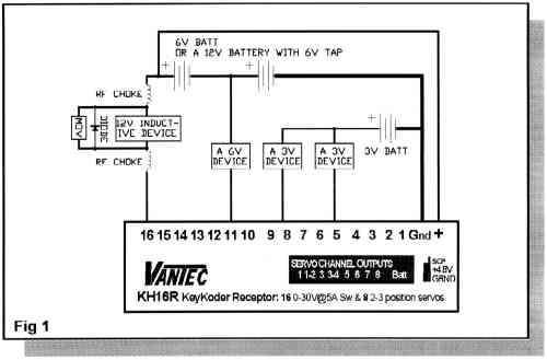
SWITCH OUTPUTS: The KH16R and KH32R Receptors have a corresponding number of 5 Ampere
on-off electronic switch outputs that operate as current sinks. This means they switch to
ground to complete the circuit to operate your device. Because they switch to ground they
easily accomodate a variety of lights, horns, motors and other loads operating on a
variety of voltages up to 30VDC by simply using different batteries or taps on a series
connected set of batteries. See Figure 1 above for examples. Total current controlled at
one time should be limited to 25 Amps.
Inductive coil loads like motors and relays inherently generate a potentially damaging
voltage spike when they are turned off. We recommend the addition of a parallel connected
flyback diode or a Metal-Oxide-Varistor (MOV) across each inductive load to safely
suppress this spike. VANTEC has supplied a number of MOVs with your HITCHIKER. They are
un-polarized so you may connect them without regard for position or orientation.
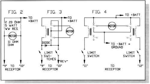
Figure 2 shows a simple "lossy" bridge circuit for forward and reverse
momentary operation of a small motor such as the zoom and focus motors found in some video
cameras. The resistors provide automatic current limiting and un-equal resistor values can
be used for different forward and reverse speeds. Experimentation is required but for 12V
battery bridge resistors should be greater than 15 ohms; 24V battery - 30 ohms. Put a MOV
across the motor brushes.
To maintain satisfactory R/C operation select quality motors whose RFI qualities are
known from past R/C applications. Some situations may require RF chokes in series; consult
VANTEC factory. Don't use toy motors with metal brushes or automobile-type horns because
these devices generate horrific RFInterference.
Relays may be used to amplify the current capacity or provide handy operating logic
such as reversing high current motors. Please use MOVs across their contacts to minimize
RFI as well as in parallel across the coil for spike supression. Additional MOVs are
available from VANTEC or Radio Shack. Use AC types rated for 30-50 volts such as Panasonic
ERZ-V05D390.
Figure 3 shows efficient operation of reversing motors up to 5 amps using a single 5
amp relay and 5 amp diode from Radio Shack. If your application runs into a physical stop
use the limit switches shown to prevent dangerous stalled motor operation. Variation:
automatic reverse/return by connecting wire "REV" to ground instead of a
Receptor output (saves a KeyKoder channel too). Don't forget the MOVs.
Figure 4 shows the use of relays to operate much larger motors, over 4 amps. In this
circuit the limit switches need only be capable of handling the relay coil current. The
automatic reverse/return idea above may be applied here also. Use MOVs.
The KH12R Receptor for airplane applications has only 4 on-off electronic switch
outputs but the same principles apply.
If the Receptor fails to receive KeyPad signals it uses the old information for a
brief time and then enters a fail safe mode. In the fail safe mode all electronic switches
are turned off except KCh14 & 15 which maintain their last state. You could use KCh14
to command lighting since your vehicle could be at rest but illuminated with the
transmitter turned off; great for dinner flotillas!
The ground circuit which supports these electronic switches to ground must be
substantial since all the current for all of your loads passes through it; up to 25 Amps.
Use #16 AWG or larger wire on the pluggable Terminal Block labeled Gnd. The ground return
for the power to run the Receptor logic itself may also be connected here.
The ideal power supply for the KH12R, KH16R or KH32R is +12VDC connected to the +
terminal of the pluggable Terminal Block. The voltage input here may range from 4.8-30VDC.
When power is not supplied to + Terminal Block then power and ground for the Receptor will
be derived automatically from the 4.8VDC power input for the Hitchiker servos as detailed
below; this is less desireable due to increased current drain.
SERVO COMMAND PULSE OUTPUTS: In addition to the electronic switches 8 of the Hitchiker
Receptor channels simultaneously have conventional Servo Command Pulse outputs that drive
regular R/C servos or speed controls to two or three pre-determined positions. Regular
plug-in servo connections are provided on the Receptor in three groups, each group
accepting 3 servo connectors; 9 Futaba "J" connectors in all. The 9th position,
on the far right, is the power input to run these 8 Receptor servos. A separate 4.8V
battery pack or 12V-to-5V power supply may be used. Servo Command Pulse outputs 1-2 and
3-4 are the three position servo outputs. The two and three positions are designed so that
a three position servo output shares a transmitter KeyPad switch with a two position servo
output. For example: KSw1 controls SCP1 which operates as as two position actuator. But
KSw1 also commands the second SCP2 servo, along with KSw2, for one of three positions.
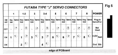
The actual servo positions are adjustable by three pots on the Receptor. They are
grouped to provide a variety of combinations but the most useful are factory set and
delineated in Fig 5.
The Receptors plug in like a servo but use a special output from the receiver.
FP-R129DP RECEIVERS come with the "C" output; plug the Receptor into the
"C" socket even if the KeyKoder has been assigned Futaba channel 5. Do not
plug a servo into the assigned channel servo connector or the "C" socket.
FP-R148DP RECEIVERS ordered from VANTEC for KeyKoder applications have been modified
with the special "C" output wired to the servo "J" connector of the
assigned channel for the KeyPad, usually Channel 5. Do not plug a servo into this channel
as it will disable all channels. If your '148 requires modification VANTEC will do it free
of charge or supply instructions to a qualified technician in your area. We do not
recommend customers modify their own receivers.
ALL RECEPTORS should keep all output wiring separated from the receiver and servo
leads. Use the full extended length of the supplied receiver antenna and locate it away
from all other wires and metal structures.
SURFACE FREQUENCIES: 75 MHz transmit modules and re-tuned FP-R148 or FP-R129P
receivers are available when ordered as a complete system; there is no additional charge
to have your transmitter legal.
There are some plausible mix 'n match possiblities between the KIK Kommander
industrial KeyKoders and the Hitchiker products: the Hitchiker transmitter add-on KeyPad
could command a KIK44 Receptor to realize sink or source MOSFET switch outputs.
The HITCHIKER comes with a limited one year warranty based upon a fixed repair
charge for units not tampered with, imersed or electrically or mechanically abused. Call
before returning unit for repair. These products are not safety devices nor for use in
life-critical or life-support systems. Specifications and prices subject to change without
notice. Patents and patent pending may apply. Some tradenames and trademarks owned by
others.
|