The KIK29 Kommander KeyKoder
is an enhanced version of the KIK20 used in battery powered remote controlled commercial
mobile robots since 1988. The KIK29 provides a radio control link featuring 14
servo channels and 15 simultaneous on-off power switch channels operating on FCC approved
frequencies with encoded transmitter identification. Up to 4 of the 15 on-off channels
include special validation coding to assure extra security against false commands. The
features outlined herein are also featured in the KIK44 which has 15 more on-off
channels. Like its predecessor, the KIK29 is based upon proven
Futaba Radio/Control technology. Futaba has established the new standard for Pulse Code
Modulation R/C systems with their PCM1024* code format. This format enables extra-reliable com-munication of control
commands. It features full 10 bit servo resolution on all 8 channels yielding over 1000
distinct servo positions for the ultimate in resolution and response. For technical
details click on The PCM Advantage. VANTEC directly interfaces with the PCM data to harness the 8th
channel as an expansion for as many as 128 additional on-off channels, or other functions
such as a unique transmitter IDentification code, more servo channels, sequential on-off
switching, a computer data port, and telemetry control.
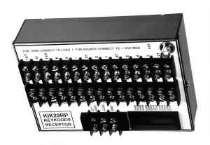
The KIK29 Receptor is designed to easily retro-fit existing
KIK20 Receptors and so is limited to 15 on-off switch outputs, transmitter identification
and two banks of 7 servo channels each. Many parameters are programmable to set the
control configuration you need. The KIK29R is 7.12"L X 5"W X 2.62"H.
The Receptor on-off switch outputs are capable of sinking or sourcing 10 amps and
withstanding 30 VDC. Because these channels may operate simultaneously there is a box
limit of 100 amperes. Each output is protected by an electronic circuit breaker at
approximately 20 amps which resets upon an "off" command.
The sink or source flexibility allows a pair of outputs to be
configured as a totem pole or half-bridge with sink to ground and source to +24 VDC. By
using a 12 volt motor connected between the totem-pole junction and a +12VDC node, the
motor may be run forward or reverse using a single Key Channel for each direction. No
relays are required. To guard against destructive totem-pole shoot-through VANTEC
coded the KeyChannels to guarantee trouble free switching. Note that a full H-bridge could
also be implemented.
The proportional channel Servo Command Pulse
outputs of the KIK29R Receptor are divided into two banks. Selected outputs provide
a +4V positive .9-2.1 ms pulse with a 14 ms repetition rate. An un-selected servo output
is low. Jumper programming establishes which channels are dedicated and which are bank
switched. Typically channels 1 & 2 are dedicated to control locomotion. The KIK29P
SCP outputs are recessed male pins just like Futaba receivers.
All communications for all channels within the KIK29 Receptor
utilize the mathematical verification built into the PCM1024 format. If the data is corrupt, it continues to use the older proven data as the
command. When the data is corrupt for approximately 1 second the receiver enters Failsafe.
You may pre-program the Failsafe response to suit your application.
VANTEC has added three additional levels of data verification
starting with specific transmitter identification. A programmable 12 bit word identifies
your transmitter about once every second; if it is not consistently received the Receptor
enters Failsafe. The Receptor also tests the KeyKoder data before updating the Key
Channel output.
The third and most critical tests are for the on-off Secure Key
Channels. For a secure output to occur:
1. No Failsafe initially or
subsequently
2. Valid PCM format
3. Valid KeyKoder device format
4. Valid specific transmitter ID received
5. Activate command received and maintained
6. Valid Trip command decoded by time and sequence sensitive
discrete hard logic.
Failsafe for the 14 Servo Command Pulse channels is
established by criteria under control of the incorporated Futaba receiver and it's effect
upon those channels is largely established by the Futaba PCM transmitter
programming as described in their manual. The Key and Secure channel Failsafe is
established by more critical VANTEC criteria within the Receptor and this Failsafe
also effects the 14 Servo channels via the bank switching multiplexer. The Key channels
response in the Failsafe mode is programmed by Receptor jumpers.
The Receptor is powered by +8 to + 12 VDC for the
+LOGIC and by the highest voltage handled by the Keykoder switch outputs connected to
+KEY; usually 24 VDC. The power on the Servo Command Pulse outputs is
derived from the +LOGIC. If these SCP outputs will not be used to run power
hungry servos a proper dropping resistor may be used between the higher +KEY power input
to run the +LOGIC. It draws 480 ma plus SCP output .
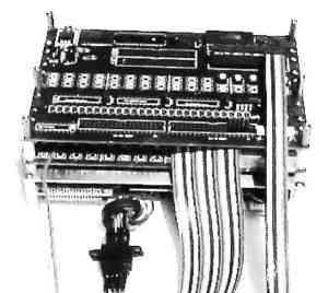
The KIK29T Transmitter is a basic building block consisting of a
sandwich of 3 Printed Wiring Boards bolted and wired together, ready for installation into
your command transmitter case or optionally VANTEC can custom package it for
you. The KIK29T is 6.9L X 4.8W X 2.7"H. Although it includes Key and Secure
channel testing buttons, connectors are provided to cable your own selection of switches,
buttons, potentiometers and joysticks. You have complete control over the control
panel design and transmitter packaging. A 18" long cable/connector kit is available
separately.
Because the Transmitter Key and Secure channels operate independently
and simultaneously a simple toggle switch serves as an accurate annunciator of the
channels status. "Latched" KeyOn/KeyOff channels are not required; but they are
available; the optional LED annunciators would be useful for such KOKO channels. A
shielded phono jack provides coaxial RF output.
The KIK29T Transmitter should be powered by 9.8 to 12 VDC. It
will cease operation below 8.8 VDC, with a warning beeping.
The license free U.S.A. R/C frequencies in the 72MHz and 75MHz bands at
.75 watt are available as standard. VANTEC has supplied other frequencies from 38.5
to 500 MHz to satisfy export markets as well as booster amplifiers up to 50 watts in
applications providing evidence of appropriate FCC licensing.
VANTEC will quote on custom packaging of the KIK29T and KIK44T
transmitters.
The KIK29 & 44 come with a limited one-year warranty based
upon a nominalrepair charge for units not tampered with or abused. Details available on our Warranty page.
We also sell a lower cost version of the KeyKoder expansion technology
called the Hitchiker for serious hobbyists.
CHOOSING THE RIGHT MODEL: See complete overview of KeyKoder
products at KeyKoder Overview. |


 DAS KOMMANDER